You are here: Panda Wiki>Cerenkov Web>FocussingLightguide (2006-07-28, KlausFoehl)Edit Attach
FocussingLightguide
Optimisation routine for lightguide coefficients
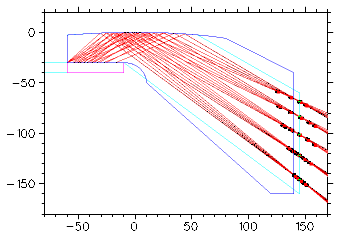 End of June 2006 I have asked our Edinburgh workshop to build two of the lightguides as shown as dark blue line in the drawing to the right, each will be 50mm thick. Slight changes like a few added holes suggested by the workshop people do not affect the optical focussing.
To obtain the shape I used a macro routine to actually optimise the lightguide shape.
Run the macro from within PHYSICA. The optimisation is one iteration only, check the quality in feeding the out values into a second iteration as input values.
For the PDF writeup and the tarball with all relevant files please see:
- 20060709.lightguide.pdf: PDF writeup
- 20060709.lightguide.tar.gz: tarball
Prior write-up
Some results on the focussing lightguides. Requirements for the two design options below were a focal plane perpendicular to the disc and a high degrees/mm dispersion. * compact focussing lightguide: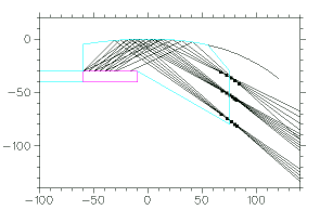
* curvedx2m54x3m09x4m05b.eps: compact focussing lightguide The black dots are focal points on a particular ray. Ideally they would all lie on top of one another. The position of a focal point actually does imply the slope of the focal plane in its vicinity. It only can be changed at the cost of imperfect focussing. The focal plane was twisted to vertical orientation to allow photon detectors to be oriented parallel to the magnetic field. The shorter the focal length, the bigger the focussing imperfections both absolute (in millimetres) and relative (in degrees or beta). The aim was here to get the dynamic range of 20degrees (45-25) into less than 50mm range, so the focal plane could be covered by a standard 50mm or 2" side length PMT. Focussing polynomial is y= -5.4/60^2*x^2 - 0.9/60^3*x^3 - 0.5/60^4*x^4
the focal plane is at x=77mm, these values can be further optimised.
Focussing imperfections [sigma]:
45deg 0.15mm ; 35deg 0.16mm ; 25deg 0.47mm .
- compact focussing lightguide with two reflections:
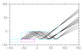
- curvedx2m54x3m09x4m05m.eps: compact focussing lightguide with two reflections
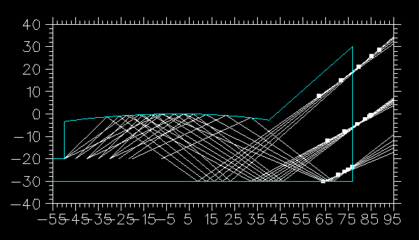
I am not happy with the focussing (sigma=0.3-0.5mm, quick hand optimisation only), and the vertical focal plane is not the best orientation either, only a compromise propagated from the Disc calculations above. Getting the focal plane perpendicular to the magnetic field may be necessary, which is good news as best focussing is achieved with somewhere between 60-80degrees and not the 90 degrees. No constraint for the focal plane orientation would be even better news... -- KlausFoehl - 06 May 2006
Photos of first Prototypes
Two focussing lightguides still assembled from polishing sandwiched between thin protective plates. Some polishing material has squeezed into the gaps. Disassembly will take place once one has decided one does not want further polishing. Each acrylic glass lightguide is 50mm thick.- Photo 1:
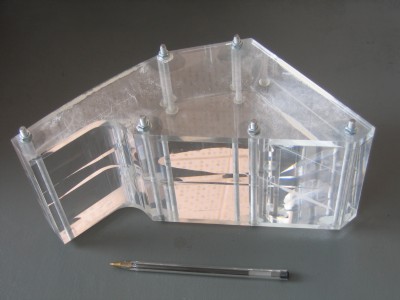
- Photo 2:
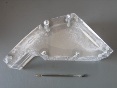
- Photo 2:
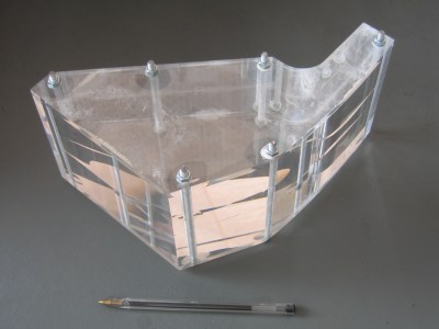
| I | Attachment | Action | Size | Date | Who | Comment |
|---|---|---|---|---|---|---|
| |
20060709.lightguide.pdf | manage | 105 K | 2006-07-09 - 15:43 | UnknownUser | PDF writeup |
| |
20060709.lightguide.tar.gz | manage | 276 K | 2006-07-09 - 15:44 | UnknownUser | tarball |
| |
curvedx2m54x3m09x4m05b.eps | manage | 22 K | 2006-05-05 - 23:23 | UnknownUser | compact focussing lightguide |
| |
curvedx2m54x3m09x4m05m.eps | manage | 10 K | 2006-05-05 - 23:29 | UnknownUser | compact focussing lightguide with two reflections |
| |
fit_proofofconceptc.gif | manage | 6 K | 2006-07-09 - 15:54 | UnknownUser | optimised lightguide |
| |
img_5488.small.jpg | manage | 22 K | 2006-07-28 - 18:42 | UnknownUser | Photo 1 |
| |
img_5489.small.jpg | manage | 18 K | 2006-07-28 - 18:43 | UnknownUser | Photo 2 |
| |
img_5490.small.jpg | manage | 20 K | 2006-07-28 - 18:43 | UnknownUser | Photo 2 |
| |
lightguidex2m50x3m10x4m10.gif | manage | 8 K | 2006-05-06 - 15:38 | UnknownUser | possible Barrel end |
| |
lightguidex2m54x3m09x4m05.gif | manage | 6 K | 2006-05-05 - 23:21 | UnknownUser | compact focussing lightguide |
| |
lightguidex2m54x3m09x4m05_.gif | manage | 4 K | 2006-05-05 - 23:48 | UnknownUser | compact focussing lightguide |
| |
lightguidex2m54x3m09x4m05mirror.gif | manage | 5 K | 2006-05-05 - 23:28 | UnknownUser | compact focussing lightguide with two reflections |
| |
lightguidex2m54x3m09x4m05mirror_.gif | manage | 4 K | 2006-05-05 - 23:49 | UnknownUser | compact focussing lightguide with two reflections |
Edit | Attach | Print version | History: r4 < r3 < r2 < r1 | Backlinks | View wiki text | Edit wiki text | More topic actions
Topic revision: r4 - 2006-07-28, KlausFoehl
Cerenkov Web
Web Home | Search Changes | Notifications Index | Topics
Web Home | Search Changes | Notifications Index | Topics
- Webs
- Cerenkov * Cerenkov.Pandacerenkov * DCS * Daq * Daq.Pandadaq * Detector * EMC * EMPAnalysis * Forwardstraws * GEM * MC * Magnet * Main * Mvd * PANDAMainz * PWA * Pbook * Personalpages * Physics * Physics.Baryons * Physics.CharmoniumAndExotics * Physics.HadronsInNuclei * Physics.OpenCharm * PhysicsCmt * SPC * STT * Sandbox * ScrutinyGroup * Tagpid * Tagpid.Pandatagpid * Tagtrk * Tagtrk.Pandatagtrk * Target * Target.ClusterJetTarget * Tof * WebServices * YoungScientists * ZArchives
Create personal sidebar
Copyright © by the contributing authors. All material on this collaboration platform is the property of the contributing authors.
Ideas, requests, problems regarding Panda Wiki Send feedback | Imprint | Privacy Policy (in German)
Ideas, requests, problems regarding Panda Wiki Send feedback | Imprint | Privacy Policy (in German)


