 |
|
You are here: Panda Wiki>Mvd Web>MvdDevelop>RoutingSpaceReq (2013-03-25, TommasoQuagli)Edit Attach
Area requirements for cables - Revision 3 (December 2012)
(Older revisions)
Detector Requirements
Pixel part
Number of supermodules: 66 Number of sensors:- 34 (2 chips size)
- 28 (4 chips size)
- 54 (5 chips size)
- 60 (6 chips size)
- 1 per sensor --> 176
- 338 (barrels)
- 472 (chips)
Strip part
Powering schemes:
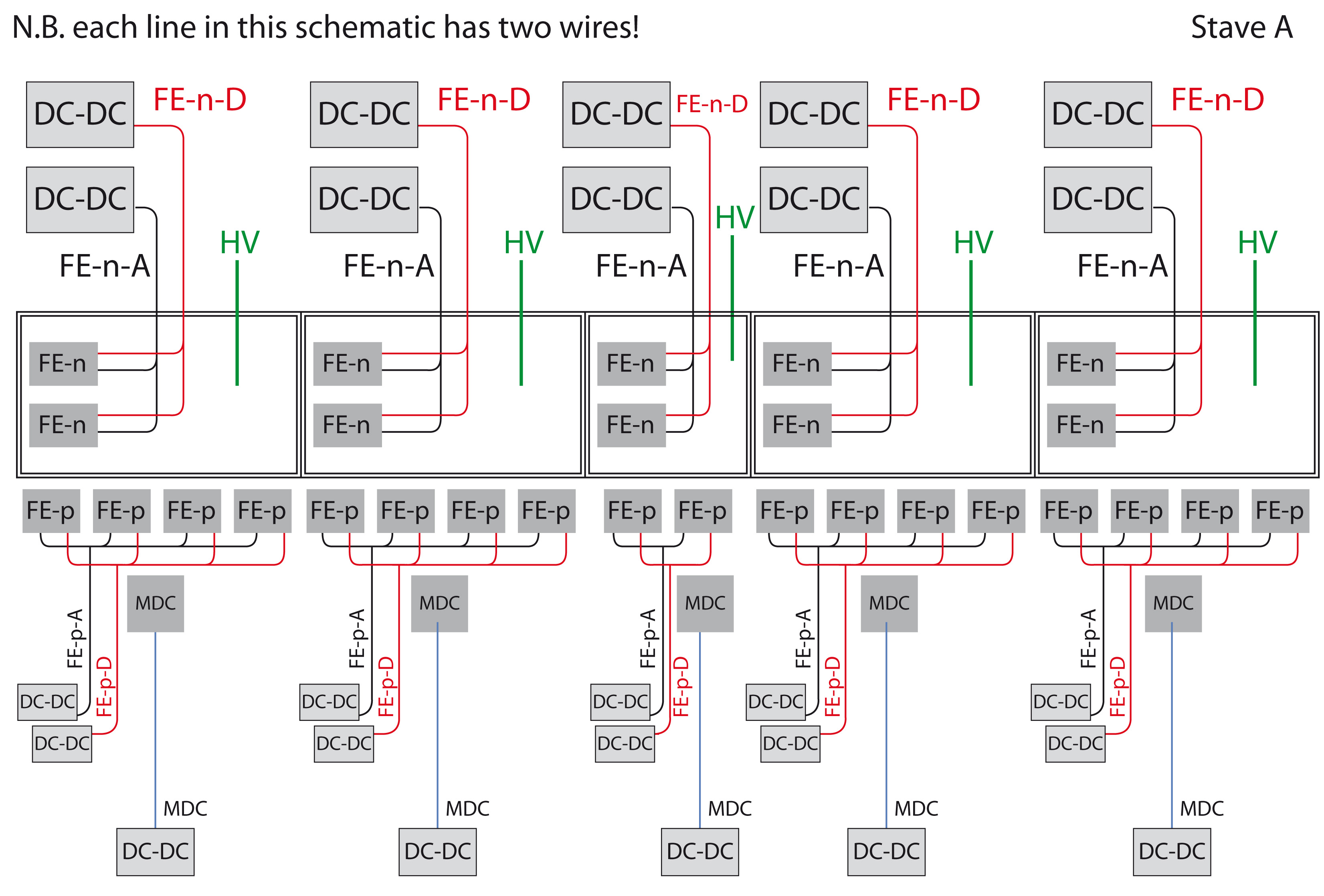
The following powering schemes were assumed for the routing calculations:- Barrel Powering scheme:
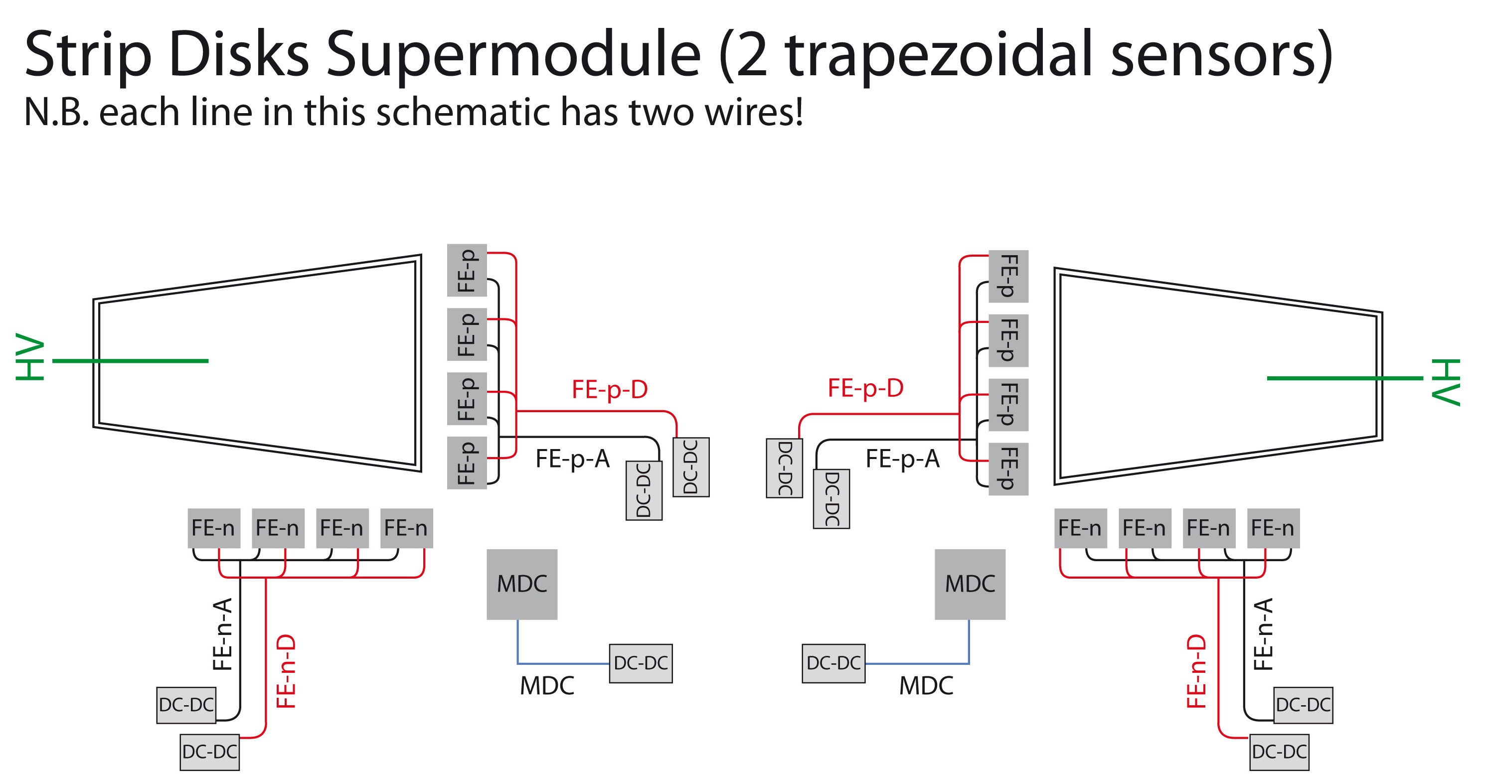
- Disk Powering scheme:
Barrel layout
The following strip barrel layout is used: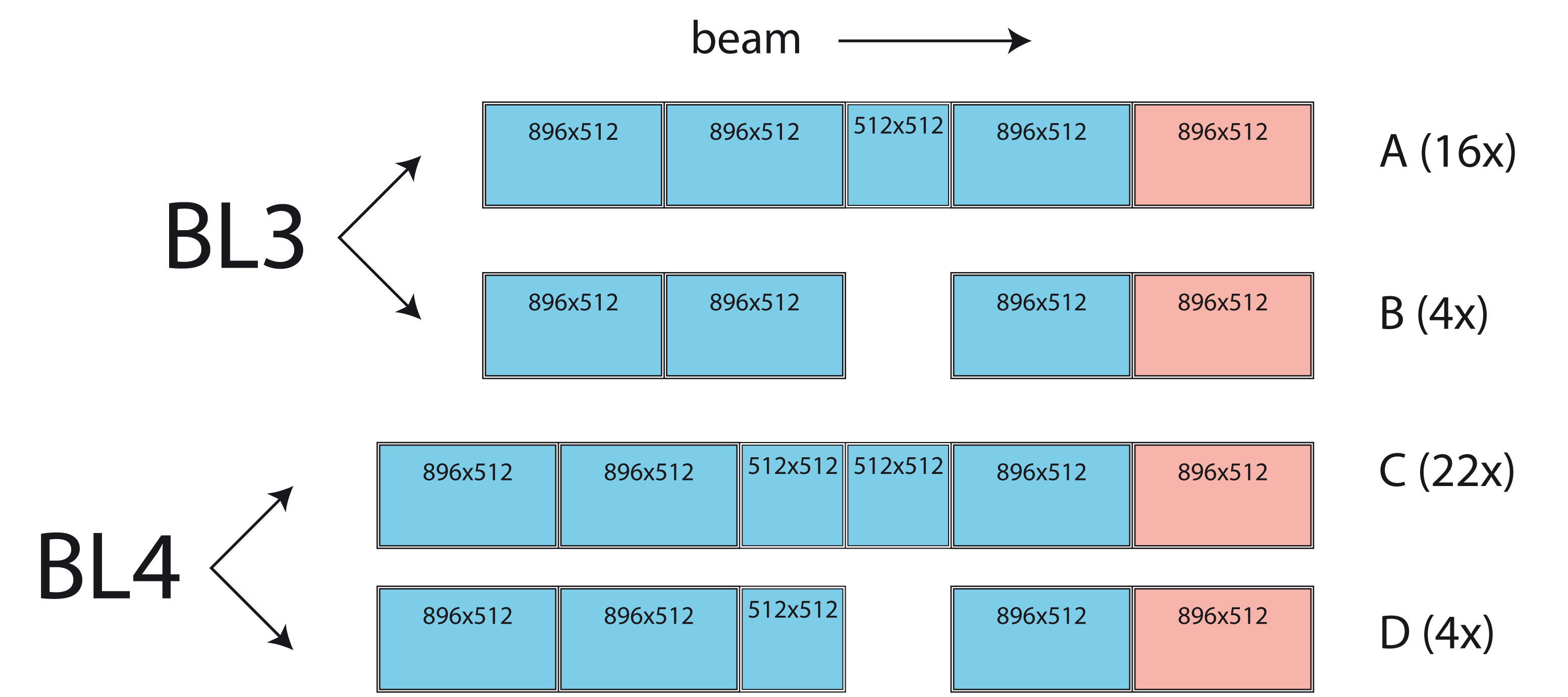 Number of staves:
 - 16 (A-type)
- 4 (B-type)
- 22 (C-type)
- 4 (D-type)
- 1176 (128 channels)
- 184 (64 channels)
- 184 (rectangular), each requiring 5x 128ch. FEs and 1x 64ch. FE
- 64 (squared), each requiring 4x 128ch. FEs
- 1 per sensor --> 248
- 1 per sensor --> 248
- n-side FEs (analog and digital)
- p-side FEs (analog and digital)
- MDC
- each "red" sensor: 2 e-links --> 46x2 = 92 e-links
- each "blue" sensor: 1 e-link --> 202 e-links
- A-type: 6 e-links
- B-type: 5 e-links
- C-type: 7 e-links
- D-type: 6 e-links
- 3 differential (= 6 single-ended) per e-link
- 16 single-ended lines per stave
- A-type: 6x6 + 16 = 52 single-ended lines
- B-type: 5x6 + 16 = 46 single-ended lines
- C-type: 7x6 + 16 = 58 single-ended lines
- D-type: 6x6 + 16 = 52 single-ended lines
- 8 e-links per board --> 294/8 = 37 boards
Disk layout
There are 24 identical supermodules, each consisting of 2 sensors. Number of sensors:- 48 (trapezoidal), each requiring 8x 128ch. FEs
- 384 (128 channels)
- each sensor: 2 e-links
- 1 per sensor --> 48
- 1 per sensor --> 48
- n-side FEs (analog and digital)
- p-side FEs (analog and digital)
- MDC
- 8 e-links per board --> 96/8 = 12 boards
- 3 differential (= 6 single-ended) per e-link
- 16 single-ended lines per stave
- per supermodule (2 sensors): 4x6 + 16 = 40 single-ended lines
Cable occupancy
Detailed calculations are available in the table and are summarized in the slides. For further details please contact TommasoQuagli. A short summary follows. The cables are divided in three categories:- from the outside to the MVD (through the GBT area) - 1
- powering of the chips (analog and digital) for strips (FE) and pixels (Topix)
- powering of the MDCs
- biasing of the sensors for pixels and strips
- from the GBT boards to the MVD - 2
- flat data cables
- from the outside to the GBT boards - 3
- powering of the GBTs
- optical fibers

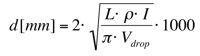
1: supply cables
Input parameters for the calculation:- power consumption:
- MDC: 0.25 A @ 2.5 V = 625 mW
- FE analog: 0.55 A @ 1.2 V = 660 mW
- FE digital: 0.3 A @ 1.2 V = 360 mW
- Topix analog: 0.2 A @ 1.2 V = 240 mW
- Topix digital: 1.2 A @ 1.2 V = 1440 mW
- cable length: 4 m
- maximum allowed voltage drop: 100 mV
- material:
- inside MVD area (cables of the disks): Al/Cu (ρ=2.65·10‐8 Ω·m)
- outside MVD area (cables of the barrels): Cu (ρ=1.68·10‐8 Ω·m)
- plastic cladding: 1mm in diameter
- Disks (Al/Cu):
- Pixels: 1008 cables, 4970 mm2
- Strips: 576 cables, 2752 mm2
- TOTAL: 1584 cables, 7722 mm2
- Barrels (Cu):
- Pixels: 616 cables, 2589 mm2
- Strips: 2976 cables, 9375 mm2
- TOTAL: 3592 cables, 11964 mm2
2: flat data cables
Cable parameters:- 18 differential pairs
- cross section 210 µm · 14 mm
- large safety factor included
- Pixels:
- Barrels: 122 cables, 427 mm2
- Disks: 196 cables, 686 mm2
- Strips:
- Barrels: 48 cables, 168 mm2
- Disks: 248 cables, 868 mm2
3: GBT cables
Input parameters for the calculation:- power consumption:
- GBT 2.5: 0.943 A @ 2.5 V = 2358 mW
- GBT 1.5: 0.425 A @ 1.5 V = 638 mW
- cable length: 3 m
- maximum allowed voltage drop: 100 mV
- material:
- Cu (ρ=1.68·10‐8 Ω·m)
- plastic cladding: 1mm in diameter
- number of GBT boards:
- Pixel barrels: 34
- Pixel disks: 88
- Strip barrels: 37
- Strip disks: 12
- Pixels: 488 cables, 1392 mm2
- Strips: 196 cables, 560 mm2
- 2 optical fibers per GBT board
- cross section 1 mm2
- 342 fibers, 342 mm2


| I | Attachment | Action | Size | Date | Who | Comment |
|---|---|---|---|---|---|---|
| |
routing-infos.pdf | manage | 645 K | 2013-03-25 - 15:34 | UnknownUser | Routing calculations summary |
| |
routing_424-10-2012.ods | manage | 37 K | 2013-03-25 - 15:35 | UnknownUser | Routing calculations detailed table |
Edit | Attach | Print version | History: r1 | Backlinks | View wiki text | Edit wiki text | More topic actions
Topic revision: r1 - 2013-03-25, TommasoQuagli
Mvd Web
Web Home | Search Changes | Notifications Index | Topics
Web Home | Search Changes | Notifications Index | Topics
- Webs
- Cerenkov * Cerenkov.Pandacerenkov * DCS * Daq * Daq.Pandadaq * Detector * EMC * EMPAnalysis * Forwardstraws * GEM * MC * Magnet * Main * Mvd * PANDAMainz * PWA * Pbook * Personalpages * Physics * Physics.Baryons * Physics.CharmoniumAndExotics * Physics.HadronsInNuclei * Physics.OpenCharm * PhysicsCmt * SPC * STT * Sandbox * ScrutinyGroup * Tagpid * Tagpid.Pandatagpid * Tagtrk * Tagtrk.Pandatagtrk * Target * Target.ClusterJetTarget * Tof * WebServices * YoungScientists * ZArchives
Create personal sidebar
Copyright © by the contributing authors. All material on this collaboration platform is the property of the contributing authors.
Ideas, requests, problems regarding Panda Wiki Send feedback | Imprint | Privacy Policy (in German)
Ideas, requests, problems regarding Panda Wiki Send feedback | Imprint | Privacy Policy (in German)